For designing and testing embedded systems, microcontrollers are utilized broadly for control electrical instruments. Keil µVision gives an across the board answer for programming embedded devices.
The µVision IDE combines project management, run-time environment, build facilities, source code editing, and program debugging in a single powerful environment. µVision programming is user friendly and quickens your embedded programming development. µVision bolsters numerous screens and permits you to make singular window designs anywhere on the visual surface. One can test, verify, and optimize their application code using the µVision Debugger single environment. The debugger incorporates customary highlights like simple and complex breakpoints, watches windows, and execution control and provides full visibility to device peripherals.
This tutorial will assist you in writing your first 8051 assembly language program using the popular Keil Compiler. Keil offers an evaluation package that will allow the assembly and debugging of files 2K or less. This bundle is openly accessible at their site www.keil.com.
Keil Tutorial Steps
Open Keil software from start menu
Click on Project-New Project
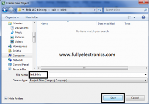
Name the project and click on Save button
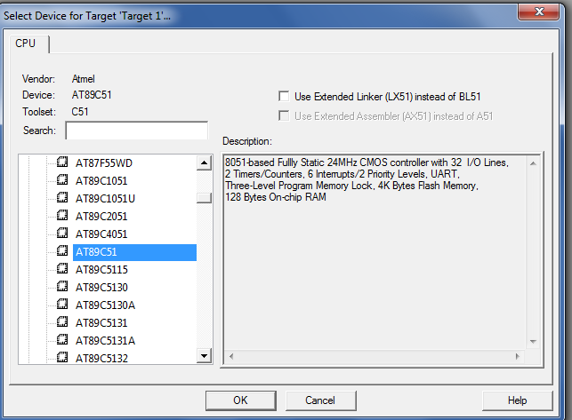
The device window will be displayed
Select the part you are working with.In this case Iam selecting AT89C51microcontroller
Create source file by clicking on File- New
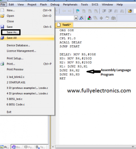
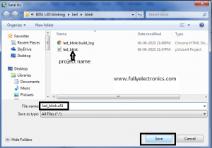
You will get a new window and write code for the required application. Then click File-Save as
Name the file with extension .asm for assembly language and .c for C language code. Make sure that both the project and source file are on the same folder. Then click on Save button.
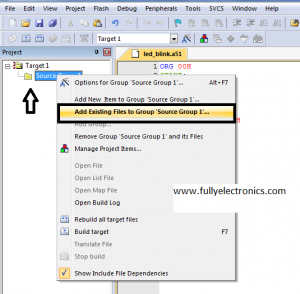
Now project and source file created. But you need to add the source file to the project. For this, you need to right-click on Target and select add existing files to Group ‘Source Group 1′
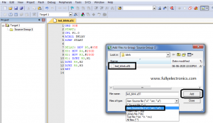
Change files of type to Asm Source file and select the already created source file. Then click on ADD button
Expand the Source Group 1 in the tree menu to ensure that file was added to the project
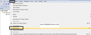
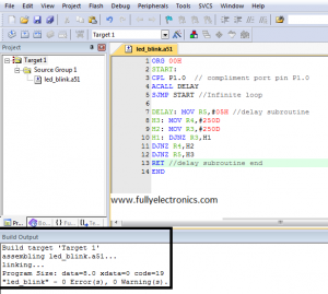
Click on Project- Build target
If your code is correct and has no errors, you will get an output window like below.
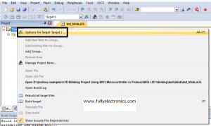
Create HEX file for the project by right-clicking on Target 1 in tree menu and select Options for Target 1
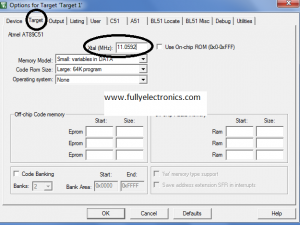
Select Target tab and change the Xtal (MHz) frequency to 11.0592
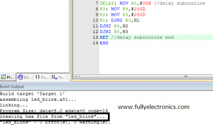
Select Output Tab and tick Create Hex File checkbox and then click OK button
Now if you again click on Project- Build Target, you can see creating the hex file line in the output window.
Click on Debug- Start Debug
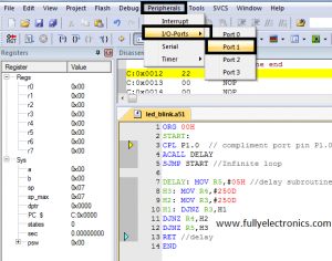
As we are looking into the example of a LED blinking program, which is connected to pin P1.0, we have to select port 1.
Go to Peripherals- I/O-Ports and select port 1.
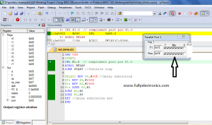
Now click on Debug- Run.You can see the port P1.0 is changing its values to 1 and 0 infinitely
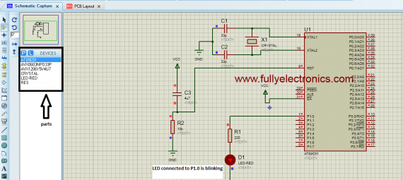
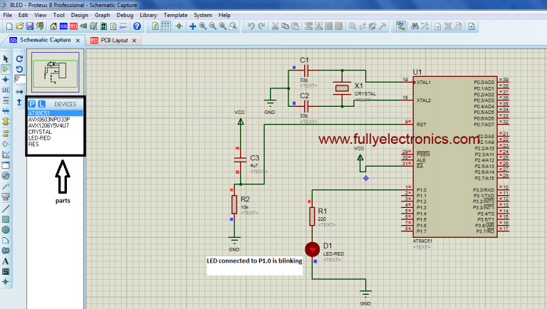
Implementation of 8051- LED example in Proteus software
LED is known as Light Emitting Diode. LED is a special type of diode that gives off visible light when forward biased. An LED always requires some means of limiting current flow through it.
ALGORITHM-Single LED 1. Start 2. Compliment the port pin P1.0 3. Call the delay subroutine go to step 2 4. Stop
PROGRAM
Single LED
ORG 00H
START: CPL P1.0
ACALL DELAY
SJMP START
DELAY: MOV R5,#05H H3: MOV R4,#250D
H2: MOV R3,#250D
H1: DJNZ R3,H1
DJNZ R4,H2
DJNZ R5,H3
RET
END
If you simulate the above code in proteus, the LED connected to pin P1.0 starts blinking. The hex file we generated will be used to burn the microcontroller.
KEIL IDE Tutorial (µVision5 for microcontroller programming)