Tinkercad is a web-based 3D modeling tool that is used to design 3D objects. It is an example of a CAD (Computer-Aided Design) software. it has become a mainstream stage for making models for 3D printing. Tinkercad utilizes a strong geometry strategy for building models. The software also included Tinkercad circuits, which permits anybody to make and simulate circuits and to program microcontroller like Arduino without the requirement for physical equipment.
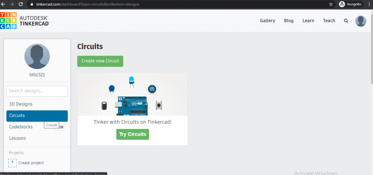
How to create a Tinkercad account?
Before you can begin making some 3D structures or to simulate circuits, you should make a Tinkercad account. Step 1) Log on to https://www.tinkercad.com Step 2) Click Join Now button on the top right corner Step 3) Click on a personal account if you are not using it for schools. You can sign up using email, Google account, Facebook account, Microsoft account, or with Apple account. Step 4) Enter your country and birthdate Step 5) Enter your email address and choose a password Step 6) Tick the agreement box, click Create Account, Click Done. Your account is successfully generated Tinkercad has a built-in tutorial that helps you learn how to use the features of the website. In this article, I will show you the fundamentals of Tinkercad Circuits and it covers how to program an Arduino in Tinkercad. Meanwhile, we will investigate the features of Tinkercad Circuits.
To start with electronics circuits, click on the circuits section on the left side of the picture. Then you will get a page with a basic example of a battery connected to a LED through a current limiting resistor.
When you click on the Start simulation button LED will be switched ON as shown below.
555 Timer- Astable Multivibrator Simulation
Similarly, we can also simulate many circuits using the components provided in the Tinkercad. One more example we can do using a 555 timer chip. The 555 IC can be configured into a wide range of different modes with just a handful of external components Therefore, it is widely used by electronics hobbyists. The below circuit shows the circuit of NE555 operated in astable multivibrator mode. This circuit flashes LED at a small-time interval using the 555 timer IC and a few other electronics components. This is a beginner project which helps to understand the fundamental standards and working of the 555 clock IC
Components required to implement the circuit in Tinkercad
555 Timer IC
Breadboard
Power supply: 9v Battery
LED
Resistors: 100 kohms, 1kohms, 1kohms
Capacitor: 1µF and 10µF
Breadboard Connectors
At first, search for breadboard and place it into the design area. The breadboard is a plastic board with a bunch of tiny holes which are arranged in a specific pattern and is used for building and testing circuits. In the below diagram, portion 1 and portion 3 have horizontal internal connections and portion 2 has two sections with internal vertical connections. Connection breaks in the middle part.
Similarly, search for other components by searching on the components list and place it on the breadboard.
After placing all the components, connect the components as per the circuit diagram given above.
You can change the color of the wire. After wiring, you can click on to start the simulation menu on the top right. LED will start flashing according to the time delay generated using R1, R2, and C1 values.
Digital Logic Gates implementation using Tinkercad
The most basic digital devices are called Logic gates. A logic gate is a circuit that has one or more input signals but only one output signal. All logic gates can be analyzed by constructing a truth table. The most basic logic gates are known as AND, OR and NOT . The other gates such as NAND, NOR, XOR, XNOR can be implemented using basic gates. The hardware logic function is implemented based on the logical algebra developed by George Boole which is called Boolean algebra in his honor. A unique characteristic of the Boolean algebra is that variables used in it can assume only one of the two values i.e either 0 or 1. Hence, every variable is either a 0 or a 1. In digital electronics circuits, we assume a voltage of 5 volt as logic 1 and ground as logic 0.
Logic Operation – AND Gate
The electronic symbol for 2-input logical AND gate and corresponding truth table is given below.
Output C is 1 when both the inputs, i.e A and B are equal to 1. AND Gate can be mathematically expressed as A.B=C The pin diagram of 74HCO8 is given below. It is a 2-input quad AND gate. For this circuit, inputs are connected to pin 1 and 2 respectively and output is connected to pin 3. Ground and VCC are pins no 7 and 14 respectively.
Tinkercad representation of Logical-AND gate
When both the inputs A and B are 0
When A=0,B=1
When A=1,B=0
When both inputs A and B are 1
Logic Operation – OR Gate
The electronic symbol and corresponding truth table for 2-input logical OR gate is given below
OR gate has an output of 1 when either A or B is equal to 1. OR gate can be mathematically expressed as A+B=C The pin diagram of 74HC32 is given below. It is a 2-input quad OR gate. For this circuit, inputs are connected to pin 1 and 2 respectively and output is connected to pin 3. Ground and VCC are pin no 7 and 14 respectively.
Tinkercad representation of Logical-OR gate
When both the inputs A and B are 0
When A=0,B=1
When A=1,B=0
When both inputs A and B are 1
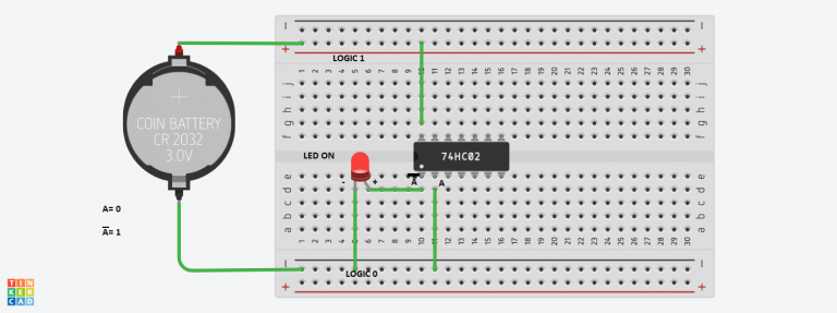
Logic Operation – NOR Gate The electronic symbol for the logic NOR gate is given below. It is called NOT Gate because the output is not the same as the input. It is also called an inverter. It has one input and one output. The schematic symbol for inversion is a small circle as below The logical symbol for inversion or negation or complementation is a bar over the function to indicate the opposite state.
The pin diagram of 74HCO2 is given below. It is a 2-input quad NOR gate. For this circuit, the input is connected to pin 2, and output is connected to pin 1. Ground and VCC are pin no 7 and 14 respectively.
Tinkercad representation of Logical-NOT gate
When input is 0
When input is 1
Similarly, you can implement NAND, NOR, XOR, and XNOR gates.
How to design and simulate circuits using Tinkercad | Beginner Level